<?xml version="1.0" encoding="UTF-8" ?>
<feed xml:lang="ja" xmlns="http://www.w3.org/2005/Atom" xmlns:dc="http://purl.org/dc/elements/1.1/" xmlns:thr="http://purl.org/syndication/thread/1.0">
  <title type="text">BFoIP ブログ</title>
  <subtitle type="html">CCNAのサンプル問題などを
英語の場合は和訳をつけて紹介します。</subtitle>
  <link rel="self" type="application/atom+xml" href="http://blog.bfoip.net/atom"/>
  <link rel="alternate" type="text/html" href="http://blog.bfoip.net/"/>
  <updated>2016-08-07T16:45:10+09:00</updated>
  <author><name>Deresuke</name></author>
  <generator uri="//www.ninja.co.jp/blog/" version="0.9">忍者ブログ</generator>
  <atom10:link xmlns:atom10="http://www.w3.org/2005/Atom" rel="hub" href="http://pubsubhubbub.appspot.com/" />
  <entry>
    <id>blog.bfoip.net://entry/13</id>
    <link rel="alternate" type="text/html" href="http://blog.bfoip.net/network/peer_has_not_completed_en" />
    <published>2017-09-26T23:16:05+09:00</published> 
    <updated>2017-09-26T23:16:05+09:00</updated> 
    <category term="Network" label="Network" />
    <title>FortiGate: VPN can&#039;t connect with this message [peer has not completed Configuration Method]</title>
    <content mode="escaped" type="text/html" xml:lang="utf-8"> 
      <![CDATA[<div>I was not able to connect Internet VPN between FortiGate and Juniper SRX.<br />
Then I found following message at the FortiGate:<br />
[<strong><span style="color: #ff0000;">peer has not completed Configuration Method</span></strong>]<br />
<br />
</div><div>---log messages-------------&nbsp;</div><div>ike 0:VPNTest:890: notify msg received: R-U-THERE-ACK</div><div>ike 0:VPNTest:VPNTest: IPsec SA connect 4 10.10.10.1-&gt;192.168.1.1:0</div><div>ike 0:VPNTest:VPNTest: using existing connection</div><div>ike 0:VPNTest:VPNTest: config found</div><div>ike 0:VPNTest: request is on the queue</div><div>ike 0: comes 192.168.1.1:500-&gt;10.10.10.1:500,ifindex=4....</div><div>ike 0: IKEv1 exchange=Quick id=b8c9b865eb29f2bb/b31f2aadaac2cb72:efeabe21 len=428</div><div>ike 0: in B8C9B865EB29F2BBB31F2AADAAC2CB7208102001EFEABE21000001AC61F3DCE0A14CE2E5F756</div><div>ike 0:VPNTest:890: <span style="color: #ff0000;">peer has not completed Configuration Method</span></div><div>ike 0:VPNTest: link is idle 4 10.10.10.1-&gt;192.168.1.1:0 dpd=1 seqno=2481</div><div>ike 0:VPNTest:890: send IKEv1 DPD probe, seqno 9345</div><div>ike 0:VPNTest:890: enc B8C9B865EB29F2BBB31F2AADAAC2CB7208100501A0EB31B500000054</div><div>ike 0:VPNTest:890: out B8C9B865EB29F2BBB31F2AADAAC2CB7208100501A0EB31B50000005C</div><div>ike 0:VPNTest:890: sent IKE msg (R-U-THERE): 10.10.10.1:500-&gt;192.168.1.1:500, len=92, id=b8c9b865eb29f2bb/b31f2aadaac2cb72:a0eb31b5</div><div>ike 0: comes 192.168.1.1:500-&gt;10.10.10.1:500,ifindex=4....</div><div>----------------<br />
<br />
If you also find this message, please try to delete following configuration on your FortiGate firewall:<br />
[set mode-cfg enable]<br />
<br />
<br />
<strong>1. Enter "<span style="color: #000000;">vpn ipsec phase1-interface</span>" mode</strong></div><div>Test-60C # config vpn ipsec phase1-interface<br />
<br />
<br />
<strong>2. Check </strong><strong><span style="color: #ff0000;">set mode-cfg enable</span>&nbsp;is listed or not on your</strong><strong>&nbsp;configuration using "show" command</strong></div><div>Test-60C (phase1-interface) # show</div><div>config vpn ipsec phase1-interface</div><div>&nbsp; &nbsp; edit "VPNTest"</div><div>&nbsp; &nbsp; &nbsp; &nbsp; set interface "wan1"</div><div>&nbsp; &nbsp; &nbsp; &nbsp; set nattraversal disable</div><div>&nbsp; &nbsp; &nbsp; &nbsp; <span style="color: #ff0000;">set mode-cfg enable</span><br />
<strong></strong></div><div>&nbsp; &nbsp; &nbsp; &nbsp; set proposal 3des-sha1 aes128-sha1</div><div>&nbsp; &nbsp; &nbsp; &nbsp; set dhgrp 5 2</div><div>&nbsp; &nbsp; &nbsp; &nbsp; set remote-gw 192.168.1.1</div><div>&nbsp; &nbsp; &nbsp; &nbsp; set psksecret ENC ooq9fO8Kc2/3JvXNaHzw==</div><div>&nbsp; &nbsp; next</div><div>end<br />
<br />
<br />
<strong>3. Delete "set mode-cfg enable"</strong></div><div>Test-60C (phase1-interface) # edit VPNTest</div><div>Test-60C (VPNTest) # set mode-cfg disable<br />
<br />
<br />
<strong>4. Confirm the configuration is deleted using show command</strong></div><div>Test-60C (VPNTest) # show</div><div>config vpn ipsec phase1-interface</div><div>&nbsp; &nbsp; edit "VPNTest"</div><div>&nbsp; &nbsp; &nbsp; &nbsp; set interface "wan1"</div><div>&nbsp; &nbsp; &nbsp; &nbsp; set nattraversal disable</div><div>&nbsp; &nbsp; &nbsp; &nbsp; set proposal 3des-sha1 aes128-sha1</div><div>&nbsp; &nbsp; &nbsp; &nbsp; set dhgrp 5 2</div><div>&nbsp; &nbsp; &nbsp; &nbsp; set remote-gw 192.168.1.1</div><div>&nbsp; &nbsp; &nbsp; &nbsp; set psksecret ENC ooq9fO8Kc2/3JvXNaHzw==</div><div>&nbsp; &nbsp; next</div><div>end<br />
<br />
<br />
<strong>5. Exit from the VPN configuration mode</strong></div><div>Test-60C (VPNTest) # next</div><div>Test-60C (phase1-interface) # end</div><div>Test-60C #&nbsp;</div><script async="" src="//pagead2.googlesyndication.com/pagead/js/adsbygoogle.js" type="text/javascript"></script><!-- Responsive --> <ins class="adsbygoogle" style="display: block;" data-ad-client="ca-pub-2181424389381393" data-ad-slot="7399199264" data-ad-format="auto"></ins><script type="text/javascript">(adsbygoogle = window.adsbygoogle || []).push({});</script>]]> 
    </content>
    <author>
            <name>Deresuke</name>
        </author>
  </entry>
  <entry>
    <id>blog.bfoip.net://entry/12</id>
    <link rel="alternate" type="text/html" href="http://blog.bfoip.net/network/peer_has_not_completed_jp" />
    <published>2017-09-26T19:48:48+09:00</published> 
    <updated>2017-09-26T19:48:48+09:00</updated> 
    <category term="Network" label="Network" />
    <title>FortiGate [peer has not completed Configuration Method]メッセージでVPN接続不可</title>
    <content mode="escaped" type="text/html" xml:lang="utf-8"> 
      <![CDATA[<div>FortiGateとSRXでVPN接続を実施しようとした際、FortiGate側で</div><div>[peer has not completed Configuration Method]というメッセージでVPNが接続できなかったときの対応をメモしておきます。<br />
<br />
---ログサンプル-------------</div><div>ike 0:VPNTest:890: notify msg received: R-U-THERE-ACK</div><div>ike 0:VPNTest:VPNTest: IPsec SA connect 4 10.10.10.1-&gt;192.168.1.1:0</div><div>ike 0:VPNTest:VPNTest: using existing connection</div><div>ike 0:VPNTest:VPNTest: config found</div><div>ike 0:VPNTest: request is on the queue</div><div>ike 0: comes 192.168.1.1:500-&gt;10.10.10.1:500,ifindex=4....</div><div>ike 0: IKEv1 exchange=Quick id=b8c9b865eb29f2bb/b31f2aadaac2cb72:efeabe21 len=428</div><div>ike 0: in B8C9B865EB29F2BBB31F2AADAAC2CB7208102001EFEABE21000001AC61F3DCE0A14CE2E5F756</div><div>ike 0:VPNTest:890: <span style="color: #ff0000;">peer has not completed Configuration Method</span></div><div>ike 0:VPNTest: link is idle 4 10.10.10.1-&gt;192.168.1.1:0 dpd=1 seqno=2481</div><div>ike 0:VPNTest:890: send IKEv1 DPD probe, seqno 9345</div><div>ike 0:VPNTest:890: enc B8C9B865EB29F2BBB31F2AADAAC2CB7208100501A0EB31B500000054</div><div>ike 0:VPNTest:890: out B8C9B865EB29F2BBB31F2AADAAC2CB7208100501A0EB31B50000005C</div><div>ike 0:VPNTest:890: sent IKE msg (R-U-THERE): 10.10.10.1:500-&gt;192.168.1.1:500, len=92, id=b8c9b865eb29f2bb/b31f2aadaac2cb72:a0eb31b5</div><div>ike 0: comes 192.168.1.1:500-&gt;10.10.10.1:500,ifindex=4....</div><div>----------------<br />
<br />
このメッセージが出た場合、[set mode-cfg enable]の設定を無効化にする必要がありました。<br />
<br />
<br />
<strong>1.vpn ipsec phase1-interface の設定モードに入る</strong></div><div>Test-60C # config vpn ipsec phase1-interface<br />
<br />
<br />
<strong>2.show コマンドで set mode-cfg enable の設定の有無を確認</strong></div><div>Test-60C (phase1-interface) # show</div><div>config vpn ipsec phase1-interface</div><div>&nbsp; &nbsp; edit "VPNTest"</div><div>&nbsp; &nbsp; &nbsp; &nbsp; set interface "wan1"</div><div>&nbsp; &nbsp; &nbsp; &nbsp; set nattraversal disable</div><div>&nbsp; &nbsp; &nbsp; &nbsp; <span style="color: #ff0000;">set mode-cfg enable</span><br />
<strong></strong></div><div>&nbsp; &nbsp; &nbsp; &nbsp; set proposal 3des-sha1 aes128-sha1</div><div>&nbsp; &nbsp; &nbsp; &nbsp; set dhgrp 5 2</div><div>&nbsp; &nbsp; &nbsp; &nbsp; set remote-gw 192.168.1.1</div><div>&nbsp; &nbsp; &nbsp; &nbsp; set psksecret ENC ooq9fO8Kc2/3JvXNaHzw==</div><div>&nbsp; &nbsp; next</div><div>end<br />
<br />
<br />
<strong>3.set mode-cfg enable 設定の無効化</strong></div><div>Test-60C (phase1-interface) # edit VPNTest</div><div>Test-60C (VPNTest) # set mode-cfg disable<br />
<br />
<br />
<strong>4.showコマンドで、設定が無効化されたことを確認</strong></div><div>&nbsp;※set mode-cfg enableが表示されないことを確認</div><div>Test-60C (VPNTest) # show</div><div>config vpn ipsec phase1-interface</div><div>&nbsp; &nbsp; edit "VPNTest"</div><div>&nbsp; &nbsp; &nbsp; &nbsp; set interface "wan1"</div><div>&nbsp; &nbsp; &nbsp; &nbsp; set nattraversal disable</div><div>&nbsp; &nbsp; &nbsp; &nbsp; set proposal 3des-sha1 aes128-sha1</div><div>&nbsp; &nbsp; &nbsp; &nbsp; set dhgrp 5 2</div><div>&nbsp; &nbsp; &nbsp; &nbsp; set remote-gw 192.168.1.1</div><div>&nbsp; &nbsp; &nbsp; &nbsp; set psksecret ENC ooq9fO8Kc2/3JvXNaHzw==</div><div>&nbsp; &nbsp; next</div><div>end<br />
<br />
<br />
<strong>5.VPN設定モードから抜ける</strong></div><div>Test-60C (VPNTest) # next</div><div>Test-60C (phase1-interface) # end</div><div>Test-60C #&nbsp;</div><script async="" src="//pagead2.googlesyndication.com/pagead/js/adsbygoogle.js" type="text/javascript"></script><!-- Responsive --> <ins class="adsbygoogle" style="display: block;" data-ad-client="ca-pub-2181424389381393" data-ad-slot="7399199264" data-ad-format="auto"></ins><script type="text/javascript">(adsbygoogle = window.adsbygoogle || []).push({});</script>]]> 
    </content>
    <author>
            <name>Deresuke</name>
        </author>
  </entry>
  <entry>
    <id>blog.bfoip.net://entry/11</id>
    <link rel="alternate" type="text/html" href="http://blog.bfoip.net/cloud/symantec%20web%20security.clou" />
    <published>2016-11-24T22:04:20+09:00</published> 
    <updated>2016-11-24T22:04:20+09:00</updated> 
    <category term="Cloud" label="Cloud" />
    <title>Symantec Web Security.cloud service transmission delay problem has been occurred.</title>
    <content mode="escaped" type="text/html" xml:lang="utf-8"> 
      <![CDATA[<div>I have suffered from this issue for 2 weeks.<br />
<br />
&lt;Symptom&gt;<br />
Slow response or sometimes you can't access to Web pages when you use Symantec .cloud　Web Security Serivce.<br />
<br />
I realized this issue on November 14th 2016 and I called to Symantec but, this issue isn't fixed yet.<br />
<br />
<br />
&lt;Current environment&gt;<br />
Out current environment is as follows:<br />
PC --&gt; domestic proxy server ---&gt; Symantec .cloud Web Security Serivce ---&gt; Web pages<br />
<br />
<br />
&lt;Isolate the cause&gt;<br />
To isolate the cause, I've done following case of connection test.<br />
<br />
1. Full path test<br />
PC --&gt; domestic proxy server ---&gt; Symantec .cloud Web Security Serivce ---&gt; Web pages<br />
Result: slow<br />
<br />
2. Except the domestic proxy server<br />
PC ---&gt; Symantec .cloud Web Security Serivce ---&gt; Web pages<br />
Result: slow<br />
<br />
3. Direct access to Web pages<br />
PC ---&gt; Web pages<br />
Result: fast<br />
<br />
<br />
From these results, the point of failure is Symantec .cloud Web Security Serivce.<br />
I hope fix it as soon as possible!</div>]]> 
    </content>
    <author>
            <name>Deresuke</name>
        </author>
  </entry>
  <entry>
    <id>blog.bfoip.net://entry/8</id>
    <link rel="alternate" type="text/html" href="http://blog.bfoip.net/sample_exam/exam_routing_20160831" />
    <published>2016-08-30T12:55:36+09:00</published> 
    <updated>2016-08-30T12:55:36+09:00</updated> 
    <category term="sample exam" label="sample exam" />
    <title>Sample exam Routing 20160831</title>
    <content mode="escaped" type="text/html" xml:lang="utf-8"> 
      <![CDATA[<div><img src="//blog.bfoip.net/File/Diagram2016083101.png" alt="" /> <img src="//blog.bfoip.net/File/Diagram2016083102.png" alt="" /> <br />
<br />
In the network diagram above, which path will packets take when travelling from host 192.168.50.126 to host 192.168.50.5?<br />
上記のネットワーク図で、192.168.50.126のホストから192.168.50.5のホストへ行く時、パケットはどのパスを通るでしょうか<br />
<br />
A. Packets will travel from R3 to R2 to R1.<br />
&nbsp;R3 -&gt; R2 -&gt; R1を通る<br />
<br />
B. Packets will travel from R1 to R3 to R2.<br />
&nbsp;R1 -&gt; R3 -&gt; R2を通る<br />
<br />
C. Packets will travel from R3 to R1 and return back to R3.<br />
&nbsp;R3 -&gt; R1 -&gt; R3を通る<br />
<br />
D, Packets will travel from R3 to R1 and from R3 to R2 to R1.<br />
&nbsp;R3 -&gt; R1 と R3 -&gt; R2 -&gt; R1を通る<br />
<br />
E. Packets will travel from R1 to R2 and back.<br />
&nbsp;R1 -&gt; R2を通って戻る</div><div><br />
<br />
<br />
<br />
<br />
<br />
<br />
<br />
</div><div>CORRECT ANSWER - D<br />
<br />
MORE INFORMATION:<br />
<br />
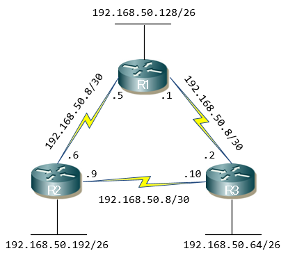
We begin by identifying to which network host 192.168.50.126 belongs.<br />
192.168.50.126がどのネットワークに属しているかを識別するところから始めます<br />
*begin by ～で始める<br />
<br />
IP address 192.168.50.126 is the last usable address for network 192.168.50.64/26, which means it is directly connected to router 3.<br />
192.168.50.126のIPアドレスは192.168.50.64/26のネットワークで使用できる最後のアドレスで、それはルータ3に</div><div>直接接続されていることを意味しています。<br />
<br />
Next, we need to identify where 192.168.50.5 is located. <br />
次に、192.168.50.5がどこにあるのかを識別する必要があります。<br />
<br />
By examining the diagram, we can see IP 192.168.50.5 is router 1's interface that connects directly with router 2.<br />
ネットワーク図を調べると、192.168.50.5のIPアドレスはルータ2に直接接続されるルータ1のインタフェースにあることがわかります。<br />
<br />
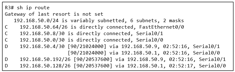
Finally, to understand the path packets will take, we examine the output of router 3's routing table and discover that there are two equal cost links to network 192.168.50.4/30, therefore EIGRP will load-balance between both paths.<br />
最後に、パケットが通るパスを理解するために、ルータ3のルーティングテーブルの出力を調べると、ネットワーク 192.168.50.4/30に対する2つの等コストリンクがあることに気づきます。</div><div>従って、EIGRPは両方のパスで負荷分散をします。</div>]]> 
    </content>
    <author>
            <name>Deresuke</name>
        </author>
  </entry>
  <entry>
    <id>blog.bfoip.net://entry/6</id>
    <link rel="alternate" type="text/html" href="http://blog.bfoip.net/sample_exam/exam_routing_20160829" />
    <published>2016-08-23T20:17:05+09:00</published> 
    <updated>2016-08-23T20:17:05+09:00</updated> 
    <category term="sample exam" label="sample exam" />
    <title>Sample exam Routing 20160829</title>
    <content mode="escaped" type="text/html" xml:lang="utf-8"> 
      <![CDATA[One of the routers in your company has just received information about network 172.16.10.0/24 from multiple sources.<br />
社内のルータが複数の送信元から172.16.10.0/24のネットワークの情報を受信しました。<br />
<br />
Which of the below will the router consider as the most reliable source for network 172.16.10.0/24?<br />
172.16.10.0/24のネットワークについてルータが最も信頼できると判断するルートは下記のうちどれか<br />
<br />
A. An EIGRP update for network 172.16.10.0/24<br />
ネットワーク172.16.10.0/24に対するEIGRPアップデート<br />
<br />
B. An OSPF update for network 172.16.10.0/24<br />
ネットワーク172.16.10.0/24に対するOSPFアップデート<br />
<br />
C. A static route to network 172.16.10.0/24<br />
ネットワーク172.16.10.0/24へのスタティックルート<br />
<br />
D. A default route with a next hop address of 172.16.0.1<br />
デフォルトルートであるネクストホップのアドレス172.16.0.1<br />
<br />
E. A directly connected interface with an IP address of 172.16.10.254/24<br />
172.16.10.254/24のIPアドレスを持つ直接接続されたインタフェース<br />
<br />
F. None of the above. The router will discard the update.<br />
上記にはない。ルータはアップデートを破棄する。<br />
<br />
<br />
<br />
<br />
<br />
<br />
<br />
<br />
<br />
<br />
<br />
<br />
<br />
<br />
<br />
<br />
CORRECT ANSWER&nbsp;-&nbsp;E<br />
<br />
The administrative distance (AD) is used by a router to determine which routing protocol to use if two or more protocols provide routing information for the same destination network.<br />
アドミニストレーティブディスタンス(AD)は、もし複数のプロトコルから同じ宛先のネットワーク情報が提供された場合に、ルータによってどのプロトコルを使用するかを決定するために使われます。<br />
<br />
The smaller the administrative distance, the higher the preference.<br />
アドミニストレーティブディスタンスが最も小さいものが最も高い優先度を持ちます。<br />
<br />
Directly connected interfaces have an AD of 0 and are always preferred.<br />
直接接続されたインタフェースはADの値が0のため、常に優先されます。<br />
<br />
Static routes have an AD of 1, while the Enhanced Interior Gateway Routing Protocol (EIGRP) has an AD of 90 and open shortest path first (OSPF) an AD of 110.<br />
スタティックルートのADは1であり、EIGRP(Enhanced Interior Gateway Routing Protocol)のADは90、OSPF(Open Shortest Path Fast)のADは110です。]]> 
    </content>
    <author>
            <name>Deresuke</name>
        </author>
  </entry>
  <entry>
    <id>blog.bfoip.net://entry/5</id>
    <link rel="alternate" type="text/html" href="http://blog.bfoip.net/sample_exam/exam_stp_20160820" />
    <published>2016-08-20T16:24:34+09:00</published> 
    <updated>2016-08-20T16:24:34+09:00</updated> 
    <category term="sample exam" label="sample exam" />
    <title>Sample exam STP 20160820</title>
    <content mode="escaped" type="text/html" xml:lang="utf-8"> 
      <![CDATA[<img src="//blog.bfoip.net/File/STP1-1.jpg" alt="" /> <br />
Your manager <span style="color: #ff0000;">has requested</span> you indicate which of the above ports will be Spanning Tree Protocol (STP)-designated ports:<br />
あなたの上司は、あなたに上記のどのポートがスパニングツリープロトコル(STP)の代表ポートかを示すようにリクエストしています。<br />
<span style="color: #ff0000;"><span style="color: #000000;">※</span>have +過去分詞</span>：&nbsp;現在完了形(～している)<br />
<br />
<br />
下記のうち、正しい代表ポートを示しているものはどちらか選びなさい<br />
A. Switch V1, Port Fa0/0; Switch V3, Port Fa0/0; Switch V3, Port Fa0/24<br />
B. Switch V1, Port Fa0/24; Switch V2, Port Fa0/0; Switch V2, Port Fa0/24<br />
<br />
<br />
<br />
<br />
<br />
<br />
<br />
<br />
<br />
<br />
<br />
CORRECT ANSWER - B<br />
<br />
<br />
The first step <span style="color: #ff0000;">is to understand</span> which switch will become the root switch.<br />
最初のステップでは、どのスイッチがルートスイッチになるかを理解するべきです。<br />
※<span style="color: #ff0000;">be to 不定詞</span>：予定、義務、可能<br />
<br />
<br />
This is done via a process called theSTP root bridge election process.&nbsp;<br />
これはSTP ルートブリッジ選出プロセスによって行われます。<br />
<br />
<br />
According to this process, the switch with the lowest bridge ID will be elected as the root switch.<br />
このプロセスによって、最も低いブリッジIDのスイッチがルートブリッジとして選ばれます。<br />
<br />
<br />
In this network diagram, that's SwitchV2.<br />
このネットワーク図で、ルートブリッジはスイッチV2です。<br />
<br />
<br />
<span style="color: #ff0000;">As per</span> STP protocol, SwitchV2 will have all ports set to STP designated.<br />
STPプロトコルによって、スイッチV2はすべてのポートをSTP代表ポート(指定ポートとも言う)にセットします<br />
&nbsp;&nbsp;<span style="color: #ff0000;"><span style="color: #000000;">※</span>as per</span>：&nbsp;～により、～の通り<br />
<br />
<br />
Ports Fa0/0 on SwitchV1 and SwitchV3 are used to reach the root switch and are therefore designated STP root ports.<br />
スイッチV1とスイッチV3のFa0/0ポートはルートスイッチに接続するために使われるため、それらはSTPルートボートに指定されます。<br />
<br />
<br />
The last set of ports to examine is Fa0/24 on SwitchV1 and SwitchV3.<br />
最後に調べる２つのポートはスイッチV1とスイッチV3のFa0/24ポートです。<br />
<br />
<br />
Between these two, one port must be set to blocking mode in order to avoid creating a loop in this network, while the other will be set to forwarding mode.<br />
これらの２つのポート間で、１つのポートは　ループを防止するためにその他のポートがフォワーディングモードにセットされる前にブロッキングモードにセットされなければなりません。<br />
<br />
<br />
<span style="color: #ff0000;">Since</span> SwitchV1 has a lower media access control (MAC) address it wins, so SwitchV1 Fa0/24 is set to forwarding and becomes an STP designated port, <span style="color: #ff0000;">while</span> SwitchV3 Fa0/24 turns to a blocking state.<br />
より小さいMACアドレスを持っているスイッチV1が勝つため、スイッチV1のFa0/24がフォワーディングモードにセットされ代表ポートになると同時に、スイッチV3のFa0/24はブロッキングモードに変わります。<br />
<br />
<span style="color: #ff0000;"><span style="color: #000000;">※</span>Since</span> ～： ～だから、～なので<br />
<span style="color: #ff0000;"><span style="color: #000000;">※</span>while</span>： ～する間、～と同時に]]> 
    </content>
    <author>
            <name>Deresuke</name>
        </author>
  </entry>
  <entry>
    <id>blog.bfoip.net://entry/4</id>
    <link rel="alternate" type="text/html" href="http://blog.bfoip.net/sample_exam/exam_ethernet_20160815" />
    <published>2016-08-15T21:30:22+09:00</published> 
    <updated>2016-08-15T21:30:22+09:00</updated> 
    <category term="sample exam" label="sample exam" />
    <title>Sample exam Ethernet 20160815</title>
    <content mode="escaped" type="text/html" xml:lang="utf-8"> 
      <![CDATA[<img src="//blog.bfoip.net/File/diagram01.jpg" alt="" /> <br />
After carefully examining the network diagram above, select the correct statement regarding broadcast and collision domains:<br />
上記のネットワーク図を良く観察してから、ブロードキャストとコリジョンドメインに関する正しい記述を選びさない<br />
<br />
A. There is one broadcast domain and seven collision domains.<br />
1個のブロードキャストドメインと7個のコリジョンドメインがある<br />
<br />
B. There are two broadcast domains and five collision domains.<br />
2個のブロードキャストドメインと5個のコリジョンドメインがある<br />
<br />
C. There is one broadcast domain and 12 collision domains.<br />
1個のブロードキャストドメインと12個のコリジョンドメインがある<br />
<br />
D. There are two broadcast domains and seven collision domains.<br />
2個のブロードキャストドメインと7個のコリジョンドメインがある<br />
<br />
E. There are two broadcast domains and 12 collision domains.<br />
2個のブロードキャストドメインと12個のコリジョンドメインがある<br />
<br />
<br />
<br />
<br />
<br />
<br />
<br />
<br />
<br />
<br />
<br />
<br />
<br />
<br />
<br />
<br />
CORRECT ANSWER - D<br />
<br />
<img src="//blog.bfoip.net/File/diagram02.jpg" alt="" /> <br />
<br />
Each link to a switch (switch port) is a separate collision domain. <br />
スイッチへのそれぞれのリンク(スイッチポート)はコリジョンドメインを分割します。<br />
<br />
In our diagram, we have two switches and a total of seven links. <br />
私達の図には、2個のスイッチと合計7個のリンクがあります。<br />
<br />
Hubs (located in the lower left corner of the image) do not create separate collision domains per link. <br />
ハブ(図の左下のかどに置かれているもの)はリンクごとにコリジョンドメインを分割しません。<br />
<br />
That's because traffic entering one port exits all other ports.<br />
ですから、1つのポートに入ったトラフィックは他のすべてのポートから出ます。<br />
<br />
Routers, on the other hand, create separate broadcast domains as broadcast packets do not propagate across them.<br />
もう一方のルータは、ブロードキャストパケットが伝搬しないブロードキャストドメインを作ります。]]> 
    </content>
    <author>
            <name>Deresuke</name>
        </author>
  </entry>
  <entry>
    <id>blog.bfoip.net://entry/3</id>
    <link rel="alternate" type="text/html" href="http://blog.bfoip.net/sample_exam/exam_protocol_20160812" />
    <published>2016-08-12T19:33:49+09:00</published> 
    <updated>2016-08-12T19:33:49+09:00</updated> 
    <category term="sample exam" label="sample exam" />
    <title>Sample exam Protocol 20160812</title>
    <content mode="escaped" type="text/html" xml:lang="utf-8"> 
      <![CDATA[Identify which of the services below use both TCP and UDP ports:<br />
TCPとUDPの両方のポートを使うサービスはどれか<br />
<br />
A. FTP<br />
B. TFTP<br />
C. DNS<br />
D. SSH<br />
E. TELNET<br />
<br />
<br />
<br />
<br />
<br />
<br />
<br />
<br />
<br />
<br />
<br />
<br />
<br />
<br />
Answer： C<br />
<br />
The domain name service (DNS) protocol is the only protocol of those listed above that uses both the Transmission Control Protocol (TCP) and the User Datagram Protocol (UDP).<br />
ドメインネームサービス(DNS)は、上記リストの中で転送制御プロトコル(TCP)とユーザデータグラムプロトコル(UDP)の両方を使う唯一のプロトコルです。<br />
<br />
UDP is the preferred transport protocol for DNS services because it's fast.<br />
UDPは速いので、DNSサービスに好まれる転送プロトコルです。<br />
<br />
UDP does not require a connection to be established between the hosts before sending any data.<br />
UDPはデータを送信する前にホスト間でコネクションの確立を要求しません。<br />
<br />
If a host fails to receive a response from a DNS server after several requests, it can then switch to TCP.<br />
もしホストが何度かリクエストした後DNSサーバからの受信に失敗したら、TCPに切り替えることができます。<br />
<br />
TCP is slower but more reliable, because it requires a three-way handshake to be established between the hosts before any data is sent.<br />
TCPは(UDPより)遅いですが信頼できます。<br />
なぜならば、データが送信される前にスリーウェイハンドシェイクを要求するからです。]]> 
    </content>
    <author>
            <name>Deresuke</name>
        </author>
  </entry>
  <entry>
    <id>blog.bfoip.net://entry/2</id>
    <link rel="alternate" type="text/html" href="http://blog.bfoip.net/sample_exam/exam_switching_20160811" />
    <published>2016-08-11T22:33:54+09:00</published> 
    <updated>2016-08-11T22:33:54+09:00</updated> 
    <category term="sample exam" label="sample exam" />
    <title>Sample exam Switching 20160811</title>
    <content mode="escaped" type="text/html" xml:lang="utf-8"> 
      <![CDATA[Host A receives a frame and discards it after determining that it is corrupt.&nbsp;<br />
At which OSI layer are frames checked for errors?<br />
ホストAはフレームを受信し、それが壊れれていると分かるとフレームを破棄します。<br />
どのOSIレイヤでフレームのエラーをチェックしますか？<br />
<br />
<br />
A. Application<br />
B. Network<br />
C. Physical<br />
D. Data-link<br />
E. FCS or CRC<br />
<br />
<br />
<br />
<br />
<br />
<br />
<br />
<br />
<br />
<br />
<br />
<br />
<br />
<br />
<br />
Answer: D<br />
<br />
The data-link layer is responsible for checking each frame received for errors.&nbsp;<br />
データリンク層には、受信した各フレームをチェックする責任があります(役割を担っています)。<br />
<br />
<br />
Every Ethernet frame includes the frame check sequence (FCS) or cyclic redundancy check (CRC) value that is calculated by the host which sent the frame.<br />
あらゆるイーサネットフレームは、フレームを送信するホスト側で計算した値である、ファイルチェックシーケンス(FCS)または巡回冗長検査符号(CRC)を含んでいます。<br />
<br />
The receiving host generates its own FCS value for every frame received and then compares it with the FCS included in the frame.&nbsp;<br />
受信側ホストは受け取ったすべてのフレームに対して自分でFCS値を計算し、フレーム内に含まれるFCSと比較します。<br />
<br />
If the FCS values match, the frame has arrived without any error.&nbsp;<br />
もしFCS値が一致していれば、フレームはエラーなしで届いたということです。<br />
<br />
If the FCS values do not match, then it is assumed that the frame has an error or is corrupt and, therefore, is discarded.<br />
もしFCS値が一致しなければ、フレームにはエラーがあるが壊れていることが推測されます。従って破棄されます。<br />
<br />
]]> 
    </content>
    <author>
            <name>Deresuke</name>
        </author>
  </entry>
</feed>